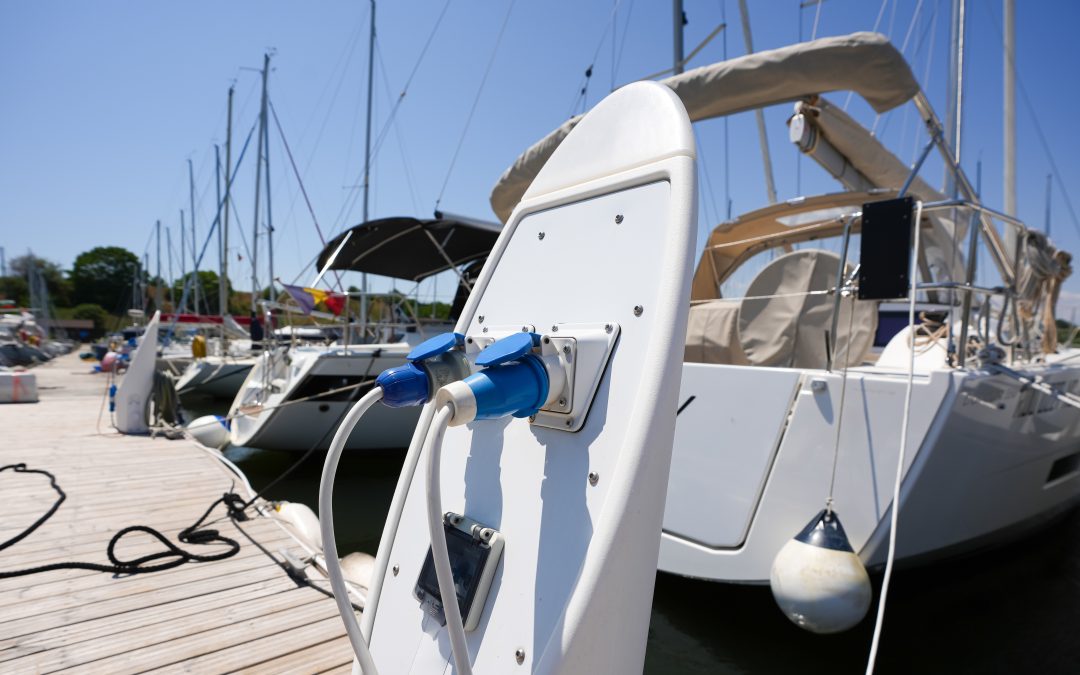
Proper electrical isolation onboard is a critical step toward ensuring the safety and reliability of your vessel. It protects your investment from galvanic corrosion, safeguards sophisticated electronics, and maintains a safer marine environment by reducing risks like Electric Shock Drowning (ESD). The American Boat & Yacht Council (ABYC) offers practical and clear guidelines through its E-11 standard, making marine electrical safety straightforward and achievable.
In this guide, we’ll take a closer look at four important isolation methods: transformer isolation (LF), galvanic isolation, polarization transformers, and high-frequency (HF) isolation. Along the way, we’ll highlight key ABYC grounding recommendations and provide clear circuit diagrams to simplify your understanding.
Transformer Isolation (Low/Line Frequency)
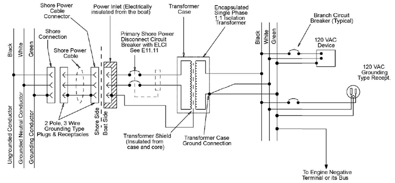
Isolation transformers provide complete electrical separation between your boat’s onboard electrical system and shore power. Think of it as an electrical firewall, fully isolating your vessel and protecting it from galvanic corrosion, shore-side faults, and significantly reducing the risk of Electric Shock Drowning.
A standout feature of isolation transformers is their secondary shield grounding. This shield is essentially a conductive barrier placed between the transformer’s primary winding and its secondary winding. It is directly connected to the dock-side ground and helps prevent unwanted stray currents from moving between these two sides. Interested in learning more about isolation transformer types and their marine compliance? You can explore further: Toroidal vs. Potted Transformers.
ABYC guidelines recommend connecting the shore-side grounding conductor directly to the transformer casing without interruptions. On your boat’s side, the transformer should have its own dedicated grounding point linked clearly to your vessel’s bonding system. Getting this right is important to avoid hazardous ground loops that could raise the risk of ESD. Specifically, ABYC E-11 recommends having just one clear bonding point, usually connected to your boat’s main DC negative bus or engine block.

Recommended Circuit Diagram (Source ABYC)
Galvanic Isolation (via Galvanic Isolators)
Galvanic isolators are simple, cost-effective devices designed to prevent galvanic corrosion. They interrupt the small, low-voltage DC currents that would otherwise flow between your boat and shore power through the grounding system. Importantly, during AC ground faults, galvanic isolators still allow current to pass, ensuring protective systems function properly.
It’s important to remember that galvanic isolators only provide limited isolation—they typically block voltages up to about 1.2–2 volts. That means they won’t protect your vessel from higher-voltage DC or AC faults. Additionally, galvanic isolators don’t guard against voltage spikes, reversed polarity, or electromagnetic interference (EMI/RFI).
ABYC standard E-11.7.2 specifies installing galvanic isolators directly within the shore grounding conductor, between your shore power inlet and the vessel’s grounding system. ABYC emphasizes choosing isolators with fail-safe features, ensuring continuous grounding even if the isolator itself fails. Regular checks and maintenance are highly recommended to maintain effectiveness.
Polarization Transformers
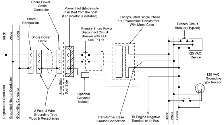
Polarization transformers help correct reversed polarity, a common issue found at marinas with older electrical setups or when cruising internationally. They align neutral and hot conductors correctly, reducing potential hazards and protecting your valuable onboard equipment.
Polarization transformers are low frequency transformers but they aren’t the same as isolation transformers. Polarization transformers work by using internal windings or autotransformer configurations that detect and correct incorrect polarity automatically. They often feature adjustable taps, providing the necessary voltage adjustments without necessarily separating input and output entirely.
These transformers don’t provide complete galvanic isolation, meaning your vessel may still be exposed to galvanic corrosion or certain shore-based electrical faults. To enhance protection, combining a polarization transformer with a galvanic isolator is a commonly recommended practice.
ABYC E-11 specifies that the shore grounding conductors must remain uninterrupted and securely bonded to your vessel’s grounding system at one central location. Special attention is recommended to prevent ground loops when polarization transformers are installed alongside other isolation systems. Additionally, properly grounding any shielding and filtering components ensures effective reduction of electromagnetic noise.
Recommended Circuit Diagram (Source ABYC E-11)
High-Frequency (HF) Isolation
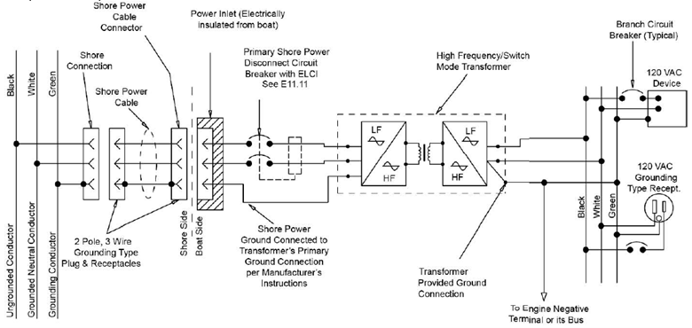
High-frequency (HF) isolation methods use specialized transformers or dedicated EMI/RFI filters to protect your onboard electronics from electromagnetic interference (EMI) and radio-frequency interference (RFI). Unlike traditional isolation transformers, HF isolation usually relies on electronic switching technology rather than conventional transformer coils.
While HF isolation methods excel at suppressing electronic interference, they do have some limitations. Generally, they don’t provide galvanic isolation, nor do they protect against voltage surges or shore-based ground faults. HF systems can add complexity, and if improperly sized or installed, might result in voltage drops or decreased system performance.
High-frequency transformer designs emphasize compactness, efficiency, reduced size, and lower weight. However, this compact design involves trade-offs. Because they rely on electronic switching devices, HF transformers can be less effective at handling high-voltage transients, require more intricate control circuits, and can introduce additional electrical noise or have increased susceptibility to component failures particularly in marine conditions.
To dive deeper into the differences between traditional and HF transformers, check out our detailed comparison here: Traditional vs. High-Frequency Transformers.
ABYC standard E-11.15 advises grounding all HF shields and filters directly to a single-point grounding conductor onboard. Following these recommendations ensures the best possible EMI/RFI noise suppression.
Recommended Circuit Diagram (Source ABYC E-11)
Comparative Summary Table
|
Feature |
Isolation Transformer |
Galvanic Isolator |
Polarization Transformer |
HF Isolation |
|
Complete Galvanic Isolation |
Yes |
No (Limited DC) |
No |
No |
|
Voltage Surge Protection |
Yes |
No |
Partial |
No |
|
Ground Fault Protection (ESD) |
High |
Limited |
Moderate |
Low |
|
ABYC Compliance |
Yes |
Yes (with limits) |
Yes (if correctly installed) |
Yes |
|
EMI/RFI Noise Reduction |
Moderate |
None |
Low |
High |
|
Corrects Reverse Polarity |
No |
No |
Yes |
No |
Selecting the right electrical isolation method is an important decision that directly impacts your vessel’s safety, reliability, and longevity. Isolation transformers offer comprehensive protection, while galvanic isolators, polarization transformers, and HF isolation each provide targeted solutions suitable for different scenarios. By carefully following ABYC grounding guidelines, you can confidently ensure your onboard electrical system remains safe, reliable, and efficient, keeping you focused on enjoying your time on the water.


