Over the past few years, ASEA has made some important changes to how our shore power converters are designed and built. If you’ve worked with the older 75kVA Vertical units, you’re probably familiar with the single/two-phase topology they’re based on. Now, with newer systems like the NV, Mega-Q, and LCZ series, we’ve moved to a 3-phase modular setup.
This post outlines the key differences between the two systems—how they work, why we made the change, and what it means for service and troubleshooting in the field.
System Design: What’s Changed?
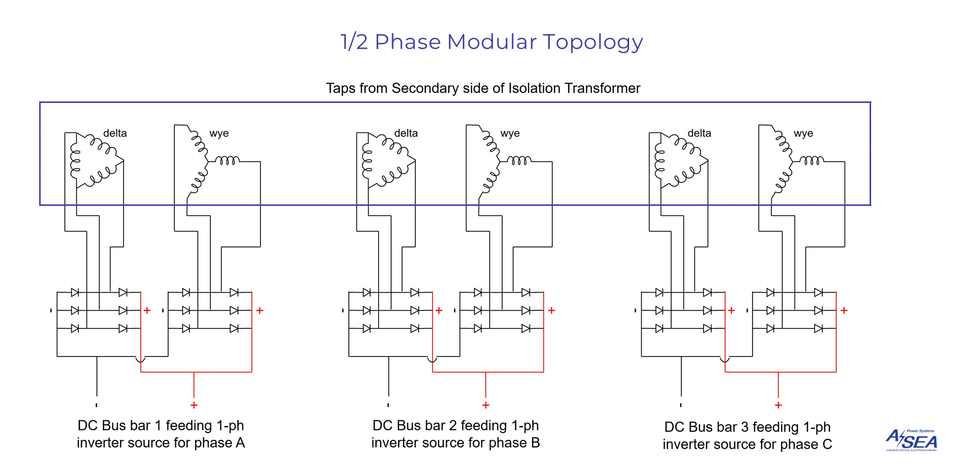
Traditional single/two-Phase Topology
The traditional 75kVA Vertical system uses a 3-phase configuration built from three independent 25kVA single-phase inverter modules, each responsible for one phase of output. This setup allows flexibility in voltage configuration: wiring the phases in parallel delivers a lower voltage output (127/220V), while wiring in series enables a higher voltage output (240/300V). Both configurations maintain the full 75kVA power capacity.
While this topology has proven reliable over the years, it does introduce complexity. Internally, each module includes six diode modules, resulting in 18 wires across the system. This not only complicates manufacturing but also makes troubleshooting and maintenance in the field more time-consuming.

Modern 3-Phase Modular Topology
Recognizing the need for smarter, more serviceable systems, ASEA began transitioning away from the single/two-phase topology in 2015, shifting focus to fully modular 3-phase systems. This evolution has shaped the –
- NV Series (air-cooled, convertible)
- the Mega-Q Series (air-cooled), and
- the LCZ Series (liquid-cooled)
—all built around a modern 3-phase modular design.
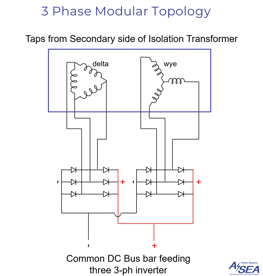
In this new architecture, each of the three modules produces all three phases in parallel. The modules work together to share the load across a true 3-phase output. One module operates as the master controller, handling synchronization, diagnostics, and system control, while the other two act as slave modules.

This shift brings significant gains in both redundancy and efficiency. A module can be removed or disabled without taking the entire unit offline. In low-load conditions, modules can also be selectively deactivated to optimize energy use, adding flexibility while improving operational efficiency.
Pros and Cons of the 3-Phase Modular System
Advantages
The new design introduces a modular mechanical layout that allows for easy removal and replacement of individual inverter modules. Since each module contains its own fuse and connects to a shared DC bus, faults can be quickly isolated and repaired without interrupting the entire system.
Reducing the diode count and simplifying internal wiring helps streamline both assembly and maintenance. With fewer components and cleaner organization inside the cabinet, service teams benefit from faster fault identification and fewer potential points of failure.
Moreover, the NV, Mega-Q, and LCZ models all offer true 3-phase output, eliminating the need to rewire the system for different voltage configurations. This simplifies installation and ensures consistent power delivery across all operating conditions.
Trade-Offs
There are some trade-offs to this new approach. The traditional system offered voltage flexibility by allowing the same hardware to deliver different outputs depending on wiring—either high or low range. The modular 3-phase systems instead offer a fixed output voltage, which simplifies setup but reduces reconfiguration options.
Another consideration is diagnostics. While the master module captures and displays comprehensive system data, the slave modules do not offer individual diagnostic interfaces. Faults in these modules must be identified visually or through data provided by the master. This is generally sufficient but may require slight adjustments in how field technicians approach troubleshooting.
The shift from a traditional single/two-phase topology to a fully modular 3-phase system reflects ASEA’s focus on improving serviceability, reducing system complexity, and enhancing overall reliability. While there are some changes to how the systems are wired and configured, the newer models are designed to be easier to support in the field and more robust over time.
If you have questions, need wiring schematics, or are looking for system training, please reach out to ASEA Technical Support at here.

