ASEA Power Systems has built its reputation by offering dependable and adaptable shore power converters designed to meet a wide range of vessel requirements. Over the years, we’ve developed and supported two distinct system architectures: the traditional single/two-phase (commonly seen in the standard, Q-series and Vertical series) and the newer 3-phase modular systems (such as the NV Series, Mega-Q, and Liquid-Cooled LCZ series).
Each of these designs offers specific advantages depending on vessel layout, power demands, and service needs. This article explores the differences between the two topologies, how each system operates, and what technicians should keep in mind when working with either setup.
How the Systems Are Designed
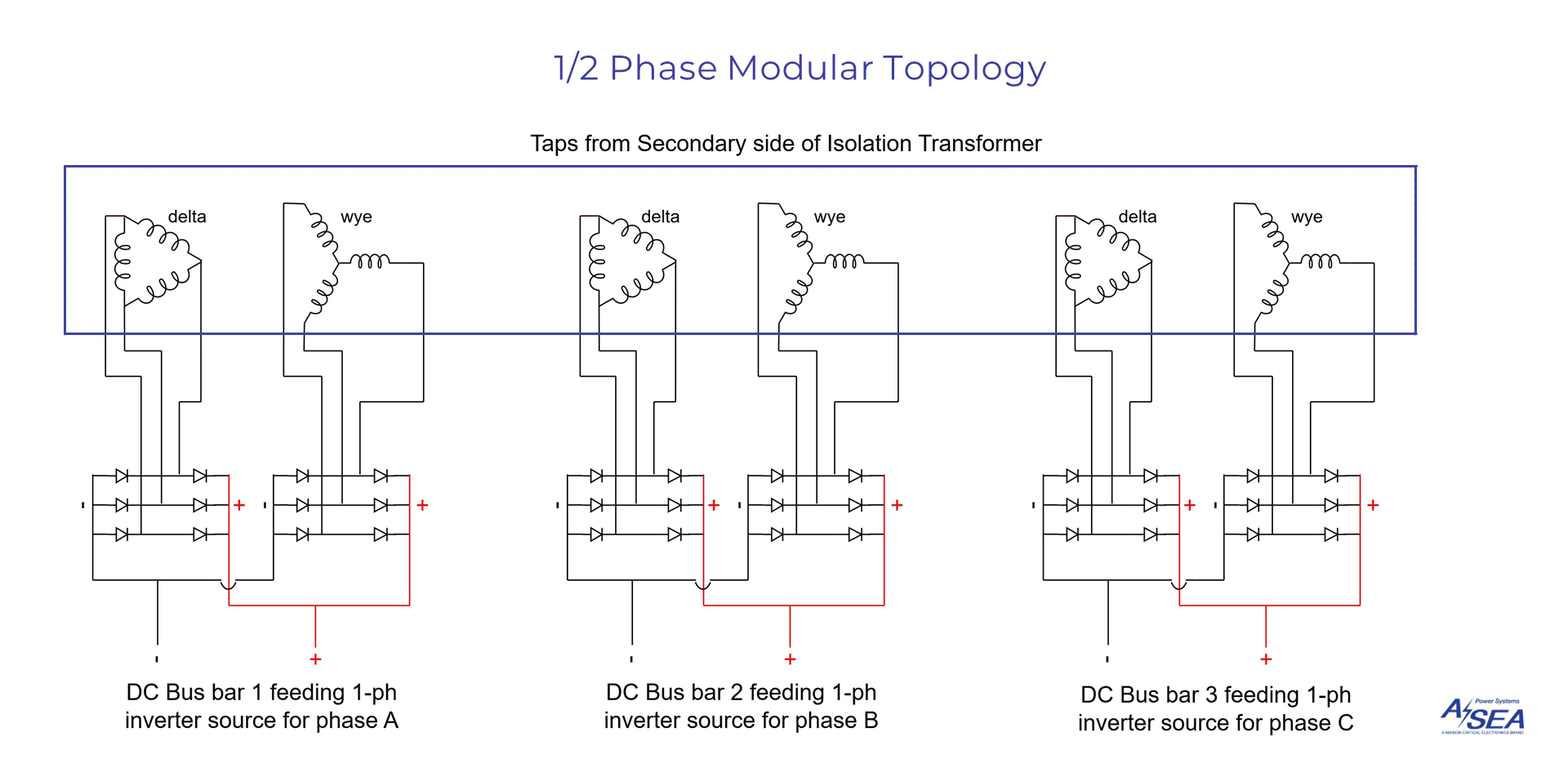
Single/Two-Phase Modular Topology
The traditional 75kVA Vertical system uses a 3-phase configuration built from three independent 25kVA single-phase inverter modules, each responsible for one phase of output. This setup allows flexibility in voltage configuration: wiring the phases in parallel delivers a lower voltage output (127/220V), while wiring in series enables a higher voltage output (240/300V). Both configurations maintain the full 75kVA power capacity.
The system is built with six diode modules across the three inverters, which increases internal wiring, 18 diodes in total. While this may make fault tracing a bit more hands-on, many service professionals are familiar with this structure and have built strong expertise in working with it.

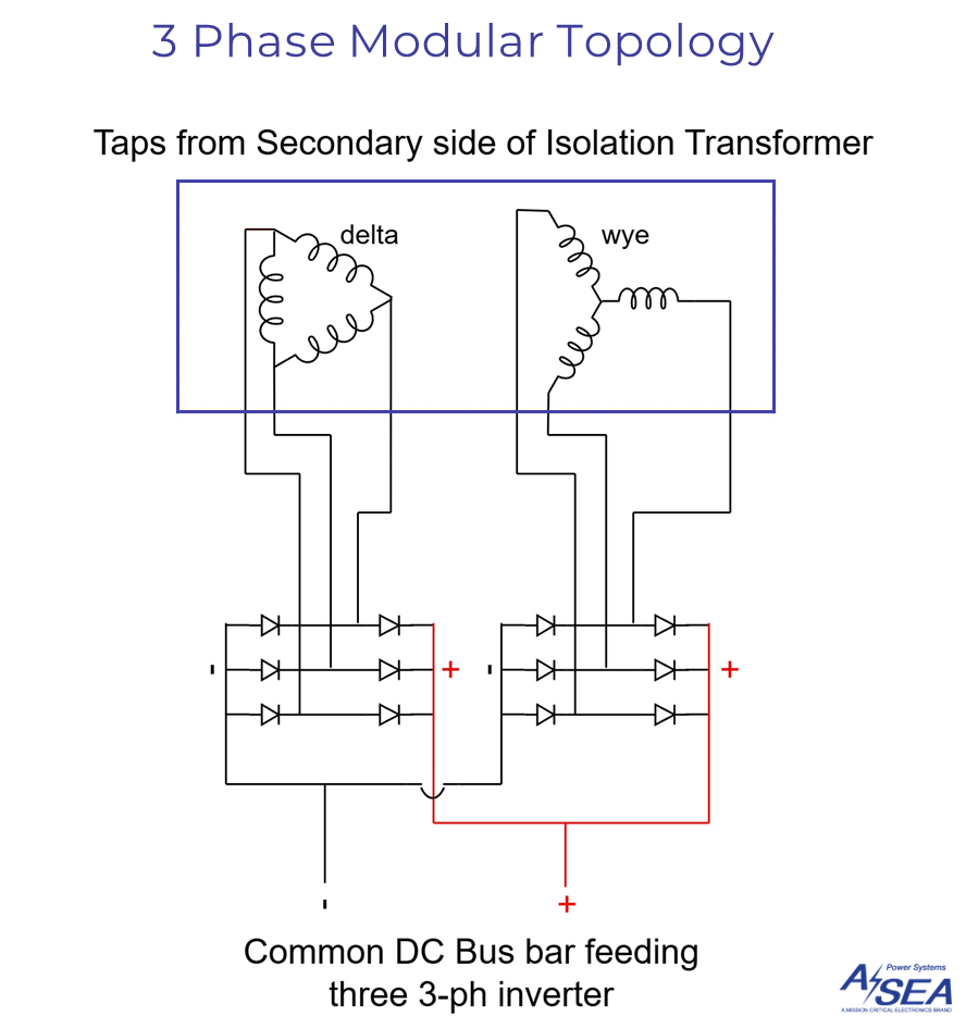
Modern 3-Phase Modular Topology
In newer systems like the NV, Mega-Q, and LCZ, ASEA uses a 3-phase modular topology. In this design, each module generates all three phases, and the system works by having all modules operate together in parallel. A master module manages synchronization and diagnostics, while the other two function as supporting modules.
This architecture simplifies some aspects of installation and service by offering a common DC bus and modular layout. It also adds flexibility in system operation—modules can be selectively turned off in low-load conditions or removed for maintenance without shutting the whole system down.

Comparing Operational and Servicing Differences
From a service perspective, both topologies are well-supported and field proven. The choice between them often comes down to the vessel’s needs, environmental conditions, and crew familiarity. Each system approaches power delivery and fault handling in its own way.
The 1/ 2-phase modular system gives the technician the ability to reconfigure voltage output based on phase wiring. This can be particularly helpful in certain installation scenarios or when retrofitting vessels with unique electrical needs. However, the separate modules and diode layout mean that more internal connections are involved, which can require extra attention during fault isolation.
The 3-phase modular systems, on the other hand, are designed with ease of service in mind. The common DC bus reduces the number of internal components and streamlines wiring. Each module is fused individually and can be removed without affecting the others. Diagnostics are centralized in the master module, offering a consolidated view of system performance and potential faults.
Both the single/two-phase and 3-phase modular topologies are valuable parts of ASEA’s product lineup. They reflect different design approaches tailored to different operational scenarios, and each brings its own strengths.
If you have questions, need wiring schematics, or other product details, please reach out to ASEA Support at here.

